
GETTING THE MOST EFFICIENT RESULTS FROM YOUR LOAD PIN INSTALLATION
Load measuring pins can be used in many different applications as replacements for clevis or pivot pins. The advantages they have over other load sensors is that they do not normally require any change to the mechanical structure being monitored. Typical applications are rope, break and chain anchors, sheaves, shackles, bearing blocks and pivots. To download this guide as a pdf, click here.
GENERAL DESCRIPTION
A load measuring pin senses the force applied across it, via strain gauges installed either internally or externally. Two grooves are machined into the pin diameter to define the shear planes, which are located between the forces being measured.
Internally mounted strain gauges lend themselves generally to withstanding harsher environments, as they are easier to seal with two end caps either welded or with o rings. In these circumstances special attention is given to the cable outlet.
Externally mounted strain gauges mounted in pockets on a shear web lend themselves to less harsh environments. This style of load measuring pin is sealed by installing potting compound over the strain gauges.
If there is an existing pin with a defined load path, then a load measuring pin can generally be installed to monitor the force being applied.
The following drawings show some typical locations for load measuring pins

Fig.1. typical pin installations
LOAD PIN ANTI ROTATION SYSTEM
A load measuring pin must be locked into position, in order to fix its orientation with respect to its associated assembly. To get the best results the load measuring pin must not be able to move in either the axial or rotation mode. The diameter of the pin needs to be machined with the most suitable tolerances for its particular application. The better the fit the better the performance. Standard load measuring pins are designed to sense a force in one direction only.
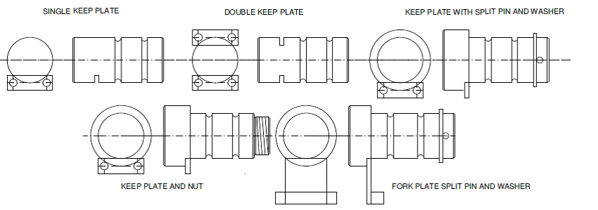
Fig.2. load pin locking methods
CABLE AND CONNECTOR OPTIONS
The signal cable can normally exit from the load pin to suit the installation and space requirements. Various options are on offer. Extra protection can be given in the form of a hose over the cable. Plug and socket options are also available, which can sometimes be recessed into the load pin. Cable has a polyurethane sheath with screen.
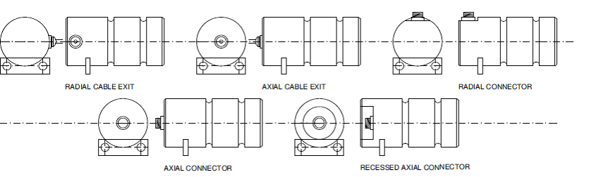
Fig.3. cable and connector options
INDIRECTLY APPLIED LOAD
A load measuring pin can be installed within a sheave system to monitor the resultant force applied to that sheave. The load applied to the wire and the wrap angle the wire makes with the sheave determines the resultant force. The following graph indicates the load on the sheave/pin versus wire load tension.
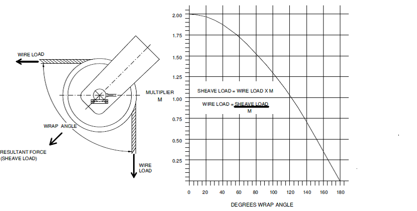
Fig.4. indirectly applied load
VARYING FORCE ANGLE
If the angle of force, as applied to the standard load pin, varies in service, either by changes in wrap angle or by some other exterior influence then there will be a loss in output as shown in the graph.
Note: up to +/- 8° of loading variation can be accommodated before a loss of 1% in signal.
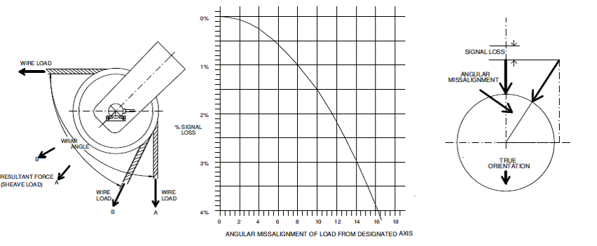
Fig.5. varying force angle
X/Y LOAD PIN
Where a high degree og angular variation is encountered then an X/Y load pin can be offered. This will give two outputs as shown in the graph. Both can be read simultaneously to compute the true resultant force applied to the load pin. The direction of force applied to the pin, can also be computed from polarity and magnitude of the X and Y signals.
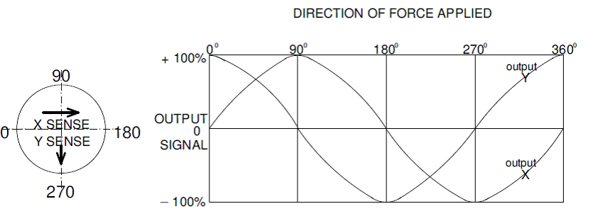
Fig.6. X/Y load pin
MATERIAL USED
A special heat treatable stainless steel is used for the manufacture of all Elite Transducers load pins. There are eight different conditions available. Hardnesses are tailored to suit varying applications. When designing a load pin there is a compromise between output signal and ultimate strength. The graph below indicates optimum load ratings for given pin diameters. Given a free hand when designing a load pin we would aim for the optimum range. However most load pins are designed to retrofit existing structures and will not always fall into this category.
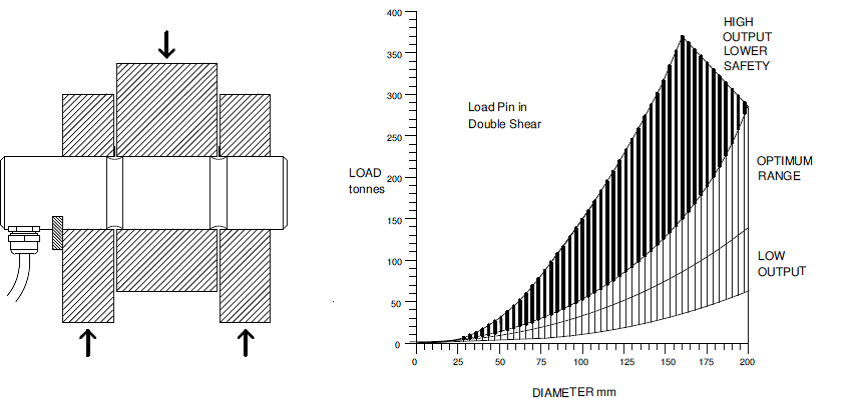
Fig.7. load rating
Armco 17-4/PH Stainless Steel Specifications
High Strength
High Hardness
Excellent Corrosion Resistance
Easy Heat Treatment
Composition
%
Carbon 0.07 max
Manganese 1.00 max
Phosphorous 0.04 max
Sulfur 0.03 max
Silicon 1.00 max
Chromium 15.00-17.50
Nickel 3.00-5.00
Copper 3.00-5.00
Colombium plus Tantalum 0.15-0.45
Condition A is normally supplied by the mill. It can then be heat treated to develop a wide range of properties. Condition H1150 is also supplied by the mill and is suitable for working in a severely cold environment. This condition is supplied with a Charpy V certificate, stating charpy impact figures at three different temperatures.